
Transforming a landmark Oxford Street property into a modern flagship retail store required far more than conventional heating and ventilation controls.
The building’s Air Handling Units needed to maintain comfortable conditions during normal retail operation while also performing a critical role within the site’s fire and smoke strategy. During a fire event, selected AHUs had to move away from ordinary temperature and air-quality control and provide dedicated make-up air to specific building zones.
This required close coordination between the AHU controls, fire-damper panels, pressure transducers, variable-speed fans and the wider Building Management System.
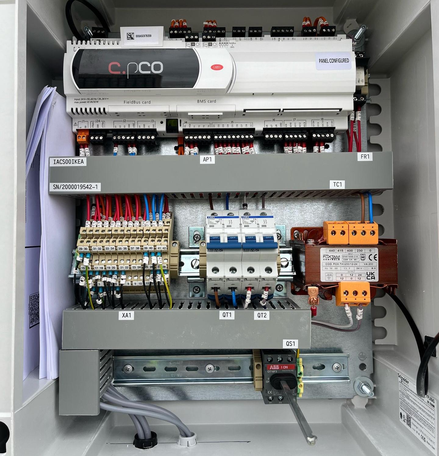
Working alongside Swegon, iACS supplied four bespoke iSmart AHU control panels and later retrofitted an additional Fire & Smoke control panel to coordinate the zoned life-safety sequences.
The project progressed from installation and panel modification through several phases of commissioning, troubleshooting and pressure balancing. iACS engineers traced third-party wiring faults, verified every fire-zone input and output, stabilised pressure-control loops and proved that the ventilation system could transition correctly between normal comfort operation and zoned fire override.
The result was a fully commissioned control architecture capable of supporting everyday retail ventilation while delivering pressure-controlled make-up air during simulated fire events.
What This Project Covered
This project demonstrates how iACS delivered:
- Four bespoke AHU control panels
- A retrofitted Fire & Smoke control panel
- Comfort ventilation controls
- Zoned fire-override sequences
- Pressure-controlled make-up air
- Variable-speed fan control
- Fire-damper panel integration
- CO₂ and temperature monitoring
- Heat-recovery control
- BMS integration
- Panel modifications
- Field wiring and point-to-point verification
- Fire-sequence testing
- Pressure P.I.D. loop tuning
- Third-party fault diagnosis
- Multi-stage installation and commissioning support
Table of Contents
- Project Overview
- The HVAC Requirements of a Flagship Retail Store
- The AHU Configuration
- Normal Comfort-Control Operation
- Why the AHUs Formed Part of the Fire Strategy
- The Dual-Panel iACS Control Architecture
- How Zoned Make-Up Air Works
- Pressure-Controlled Fan Operation
- Integration with the Mandik Fire Panels
- Installation and Panel Modifications
- Preparing the Systems for Commissioning
- The Constant Fire-Override Fault
- Testing the Fire-Zone Inputs and Outputs
- Resolving Fan Hunting
- Balancing the Pressure Zones
- BMS Integration and Functional Verification
- Commissioning Across Multiple Visits
- The Project Outcome
- Why This Project Matters
- Key Capabilities Demonstrated
- Looking for a Specialist Life-Safety Controls Partner?
1. Project Overview
Customer
Swegon Ltd
End User
IKEA Oxford Street
Sector
Retail and Commercial
Application
Flagship-store ventilation and fire-safety integration.
Project Location
Oxford Street, London
Project Period
Installation began in 2024, with extensive commissioning and fire-system integration continuing through 2025.
iACS Scope
- AHU control-panel supply
- Fire & Smoke panel retrofit
- Control-panel modifications
- HVAC field integration
- Zoned pressure-control software
- Mandik fire-panel interfacing
- BMS integration
- Installation support
- Functional testing
- P.I.D. loop tuning
- Fire-sequence commissioning
-
Handover documentation
AHU Equipment
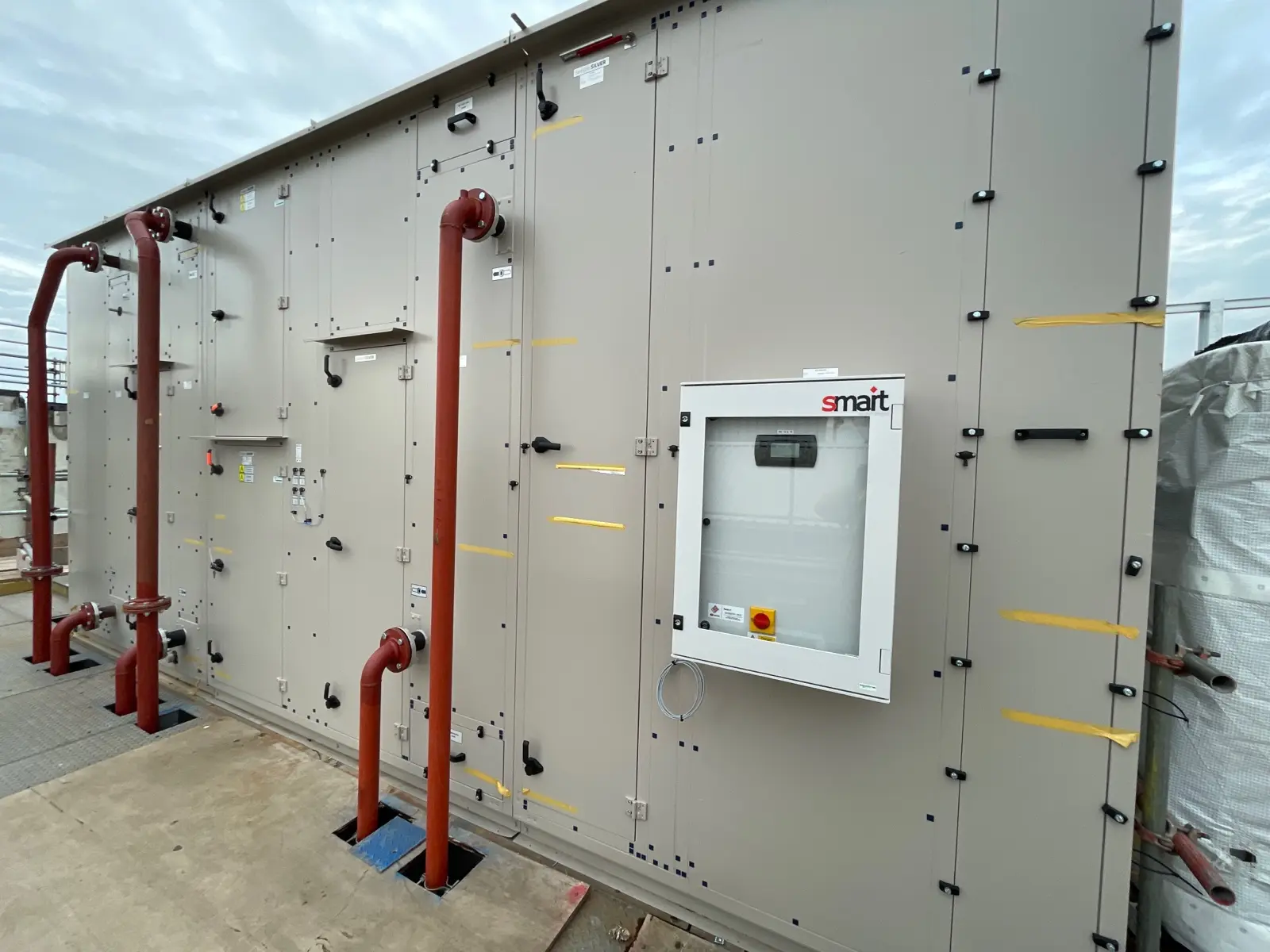
The installation included four main Swegon Silver AHU systems serving different areas of the building.
The project records identify unit groups including:
- AHU 1A and 1B
- AHU 2A and 2B
- AHU 3
- AHU 4A and 4B
The units were installed on a purpose-built rooftop plant platform and incorporated supply and extract fans, temperature and CO₂ sensing, frost protection, heat recovery and pressure monitoring.
Control Solution
- Four iACS iSmart AHU control panels
- One dedicated zoned Fire & Smoke control panel
- Integration with third-party Mandik fire-damper panels
-
Full BMS communication
Project Status
Commissioned and handed over.
2. The HVAC Requirements of a Flagship Retail Store
Large retail developments experience constantly changing environmental loads.
Occupancy can vary significantly throughout the day, particularly at a flagship Oxford Street location where multiple floors may accommodate large numbers of visitors.
The HVAC system must respond to:
- Changing customer numbers
- Internal heat gains
- External weather conditions
- Store opening schedules
- CO₂ levels
- Heating and cooling demand
- Air-quality requirements
- Fire and smoke conditions
During ordinary operation, the AHUs were required to provide comfortable, energy-conscious ventilation throughout the store.
However, the same ventilation infrastructure also formed part of the building’s life-safety strategy.
This meant the controls could not be designed solely around temperature and air quality. They also needed to coordinate precisely with the building’s fire systems.
3. The AHU Configuration
The Swegon Silver AHUs provided the main ventilation functions for the development.
The systems included:
Variable-Speed Supply Fans
The supply fans delivered fresh and conditioned air into the building.
Variable-speed control allowed the airflow to respond to normal HVAC demand and, during fire operation, to the required pressure setpoint for the active zone.
Extract and Return Fans
The extract systems supported normal ventilation and the wider smoke-management strategy.
Temperature Sensors
Supply, return and outdoor-air temperatures were monitored to support normal AHU control.
CO₂ Monitoring
Duct-mounted CO₂ sensors allowed the ventilation strategy to respond to indoor air-quality demand during normal occupancy.
Pressure Transducers
Pressure transducers measured duct static pressure during fire mode and provided the feedback required for zoned fan-speed control.
Heat Recovery
The AHUs incorporated heat-recovery functionality to reduce energy demand during normal operation.
Frost Protection
Frost protection devices helped protect the AHUs during low-temperature conditions.
Fire and Smoke Interfaces
The AHU panels received zone-specific signals from the building’s fire-control equipment, allowing ordinary comfort operation to be overridden when required.
4. Normal Comfort-Control Operation
Under normal conditions, the four iSmart panels managed the standard AHU control sequences.
These included:
- Supply-air temperature control
- Return-air monitoring
- Fan enable and speed control
- CO₂-based ventilation demand
- Heat-recovery operation
- Frost protection
- Filter and airflow monitoring
- Alarm handling
- BMS communication
The iSmart panels used P.I.D. control loops to regulate system outputs smoothly rather than simply switching equipment between fully on and fully off.
This allowed the systems to maintain stable comfort conditions while adapting to changes in store occupancy and environmental demand.
The normal control strategy remained active until a valid fire-zone signal was received.
5.
Why the AHUs Formed Part of the Fire Strategy
In many buildings, a fire alarm simply shuts the AHU down.
This project required a more complex response.
During a fire event, the ventilation system needed to provide make-up air to selected areas of the building. Make-up air replaces air removed by the smoke-extract system and helps establish the intended airflow paths through the building.
Depending on the active zone, the AHUs had to:
- Exit normal comfort-control operation.
- Receive a zone command from the fire system.
- Start or maintain the appropriate supply fans.
- Open the required airflow path.
- Regulate the fans against a defined duct-pressure target.
- Maintain the required make-up air for that zone.
- Report operating status and alarms.
- Return to normal operation only when the fire sequence was correctly cleared.
This required the AHU controls to coordinate with the wider fire strategy rather than acting as standalone ventilation systems.
6. The Dual-Panel iACS Control Architecture
To manage both ordinary HVAC control and the specialist fire sequences, iACS used a dual-panel arrangement.
iSmart AHU Control Panels
Four iSmart panels managed the everyday AHU functions.
These panels controlled:
- Temperature
- Air quality
- Fans
- Heat recovery
- Frost protection
- HVAC alarms
- Standard operating schedules
-
BMS communications
Dedicated Fire & Smoke Control Panel
The additional Fire & Smoke panel managed the emergency override functions.
It interfaced directly with the Mandik fire-damper panels and received the active fire-zone signals.
When a valid zone command was detected, the Fire & Smoke panel overrode the normal comfort strategy and instructed the relevant AHU controls to operate according to the fire sequence.
This separated the everyday comfort logic from the specialist life-safety control while allowing the two systems to work together.
7. How Zoned Make-Up Air Works
The building was divided into multiple fire-control zones.
Each zone required a different ventilation response.
The Fire & Smoke panel therefore needed to determine:
- Which zone was active
- Which AHU or fan arrangement was required
- Which duct-pressure setpoint should apply
- Whether the associated dampers were in the correct state
- Whether the fans had started successfully
- Whether the measured pressure had reached the required level
The process can be summarised as follows:
Step 1 - Fire-Zone Signal Received
A zone input is received from the Mandik fire-control equipment.
Step 2 - Normal HVAC Control Is Overridden
Temperature, CO₂ and scheduling demands no longer determine the primary fan response.
Step 3 - Zone-Specific Pressure Setpoint Is Selected
The controller loads the pressure target assigned to the active fire zone.
Step 4 - Fans Start
The appropriate supply fan arrangement is enabled.
Step 5 - Pressure Feedback Is Monitored
The duct pressure transducer reports the live static pressure.
Step 6 - Fan Speed Is Modulated
The controller increases or decreases fan demand until the required zone pressure is maintained.
Step 7 - Status Is Verified
Fan, pressure, damper and alarm information is checked before the sequence is considered proven.
This approach allows one AHU system to support different parts of the fire strategy according to the location of the active event.
8. Pressure-Controlled Fan Operation
During ordinary HVAC operation, fan speed may be controlled according to ventilation, temperature or air-quality demand.
During the fire sequence, the control priority changed to duct static pressure.
The fan P.I.D. loop compared:
- The active zone pressure setpoint
- The pressure measured by the transducer
If pressure was below target, fan demand increased.
If pressure was above target, fan demand reduced.
This allowed the AHUs to maintain the required make-up air despite changes in damper position and system resistance.
The project documentation records zone setpoints and operating values such as:
- Zone 1 operating around 380 Pa at approximately 75% fan speed during one stage of testing
- Zone 4 using a 500 Pa control target with fan demand restricted to approximately 60% during troubleshooting
- Subsequent AHU 2 balancing that included approximately 585 Pa for Zone 1 and 140 Pa for Zone 4
These values relate to specific commissioning conditions and demonstrate that each AHU and zone had to be tuned and proven individually rather than relying on one universal fan setting.
9.
Integration with the Mandik Fire Panels
The site’s Mandik panels formed an important part of the fire and smoke system.
The iACS Fire & Smoke panel exchanged zone and status signals with this third-party equipment.
The integration needed to ensure:
- The correct fire zone was identified
- The correct AHU override was selected
- False or persistent signals were detected
- Fans did not remain in emergency operation after the sequence cleared
- All control-panel inputs and outputs matched the agreed fire matrix
- Communication faults could be identified during testing
Life-safety integration cannot be validated from software alone.
Every physical signal must be checked from end to end, including:
- Source panel output
- Field wiring
- Terminal connection
- iACS input state
- Software interpretation
- Output command
- Final equipment response
This became especially important when the project encountered an external wiring fault.
10.
Installation and Panel Modifications
Installation work began with the integration of the AHU control panels and associated field devices.
The project also required modifications to support the fire and smoke interfaces.
The earlier site documentation records work including:
- Installation of the Fire & Smoke control panel
- Completion of interconnecting wiring
- Replacement of original two-pole relays with four-pole relays
- Installation of additional terminals
- Reconfiguration of the panel for the smoke-control interface
- Fan-operation checks
- Alarm checks
- Damper-operation verification
- Point-to-point testing
- Earth-continuity testing
The panel modifications allowed the iSmart controls and dedicated fire system to exchange the additional signals required by the project.
This is an example of iACS adapting a control solution to the building’s real operating requirements rather than treating the originally supplied panel as fixed and unchangeable.
11.
Preparing the Systems for Commissioning
Before final fire-sequence testing, the normal AHU functions had to be commissioned.
The site reports document checks involving:
- Supply-air temperature sensors
- Return-air temperature sensors
- Outdoor-air temperature sensors
- CO₂ sensors
- Off-coil temperature sensors
- Supply pressure transducers
- Extract pressure transducers
- Supply and extract fans
- Damper actuators
- Heating coils
- Cooling coils
- Heat-recovery equipment
- Frost protection
- BMS communications
Several outstanding site conditions were identified and documented during this process, including incomplete sensor installation, previous water damage to sensors and unfinished fire-alarm terminations.
Rather than hiding these issues, the commissioning reports created a clear record of:
- What had been tested
- What was operational
- What required correction
- Which trade was responsible
- What needed to be revisited
This structured approach helped the wider project team progress toward final fire verification.
12.
The Constant Fire-Override Fault
During fire commissioning, one AHU remained continuously in the Zone 4 override state.
The controller appeared to be receiving an active fire command even when the system should have returned to normal operation.
The iACS engineer investigated the complete signal path rather than assuming that the software was at fault.
Testing established that the third-party fire-panel wiring was supplying a constant signal of approximately 27V into the iACS Zone 4 input.
From the controller’s perspective, this represented a valid and continuously active fire condition.
The AHU therefore remained in emergency operation exactly as programmed.
How the Fault Was Resolved
iACS worked with the site electrical team to:
- Identify the affected input
- Measure the incoming voltage
- Trace the source of the permanent signal
- Check the Mandik panel output
- Correct the external wiring
- Re-test the iACS input
- Confirm the override cleared correctly
- Prove normal comfort operation could resume
- Re-test the genuine Zone 4 command
This fault demonstrates why fire commissioning must involve the complete integrated system. A correctly programmed controller cannot distinguish between a genuine fire signal and an incorrectly wired permanent input without physical testing and engineering investigation.
13.
Testing the Fire-Zone Inputs and Outputs
Once the wiring fault had been addressed, the project team completed systematic testing of the fire interfaces.
For each zone, the tests needed to verify:
- The correct Mandik output operated.
- The corresponding iACS input changed state.
- The Fire & Smoke panel selected the correct sequence.
- Normal HVAC control was overridden.
- The intended fan arrangement started.
- The correct pressure setpoint became active.
- Damper and fan statuses were proven.
- Alarms were correctly reported.
- The sequence cleared appropriately when reset.
Testing every zone individually was essential because a fault affecting only one input or output could compromise the response within one part of the building while the remaining zones appeared to operate normally.
The documented commissioning process confirmed that the zone signals and BMS communications were progressively established and proven.
14.
Resolving Fan Hunting
A second major technical issue involved unstable fan operation.
During pressure control, the supply fans repeatedly accelerated and decelerated instead of settling at a stable speed.
This behaviour is commonly described as hunting.
Why Fan Hunting Happens
Fan hunting can occur when:
- The P.I.D. loop reacts too aggressively
- Pressure readings fluctuate
- The integral action accumulates too quickly
- The fan response is faster than the duct system
- The pressure sensor is affected by turbulence
- Damper movements alter system resistance
- The control deadband is too narrow
In a life-safety application, unstable fan control is particularly problematic because the system must maintain a dependable pressure rather than oscillating around it.
The iACS Response
An iACS commissioning specialist reviewed:
- The live pressure value
- The active setpoint
- Fan-speed demand
- P.I.D. proportional response
- Integral timing
- Pressure-transducer behaviour
- Damper positions
- Zone sequence
- Minimum and maximum fan limits
The P.I.D. loops were then adjusted to dampen the response and allow the pressure to stabilise.
For certain commissioning stages, fan demand was also constrained to provide a controlled operating point while the target pressure was proven.
These adjustments eliminated the rapid fan-speed fluctuations and allowed each active zone to settle closer to its intended pressure target.
15.
Balancing the Pressure Zones
Each AHU and fire zone created a different airflow path through the building.
The resistance of those paths depended on factors such as:
- Duct length
- Duct size
- Damper position
- Number of open branches
- Grille resistance
- Smoke-control arrangement
- Leakage
- Active zone configuration
One fan-speed value could therefore not be assumed to produce the correct pressure in every zone.
The commissioning process required the team to activate each zone and observe:
- Pressure setpoint
- Measured pressure
- Fan-speed command
- Stability
- Time taken to settle
- Damper status
- Associated alarms
The resulting control settings were adjusted to suit the behaviour of the live system.
The project records confirm that pressure zones were successfully balanced against their specified targets, including separately documented values for AHU 2.
16.
BMS Integration and Functional Verification
The AHU controls were integrated with the wider site BMS.
During commissioning, the iACS team verified that relevant data could be monitored and exchanged successfully.
The BMS integration included information such as:
- AHU operating status
- Temperature values
- CO₂ readings
- Fan speeds
- Pressure readings
- Active fire zone
- Fire override status
- Fan alarms
- Sensor faults
- General system alarms
- Comfort and fire operating modes
The AHUs needed to remain visible to the building operators during both ordinary and emergency operation.
However, the fire sequence remained controlled through the dedicated life-safety interfaces rather than being dependent solely on high-level BMS communication.
This approach preserved the required hardwired response while still giving facilities teams central visibility of the system.
17.
Commissioning Across Multiple Visits
The complexity of the installation meant that commissioning was not completed in a single short visit.
The project required phased attendance to address:
- Installation readiness
- Sensor checks
- Normal AHU operation
- BMS communications
- Fire-panel interfaces
- Zone-by-zone testing
- Wiring corrections
- Fan stability
- Pressure balancing
- Final verification
This reflects the reality of commissioning complex life-safety systems in an active construction environment.
Different elements of the installation may become available at different times, and third-party equipment must often be completed before the full sequence can be tested.
The documented site reports created continuity between visits and allowed each engineer to understand the current system status, changes made and remaining actions.
18.
The Project Outcome
Following the wiring rectification and pressure-loop tuning, the controls were subjected to full fire and smoke verification.
The completed system demonstrated that it could:
- Operate the AHUs normally under iSmart comfort control
- Monitor temperature and CO₂ demand
- Communicate with the site BMS
- Detect the active fire zone
- Override the standard HVAC strategy
- Select the appropriate pressure target
- Run the required supply fans
- Modulate fan speed using live pressure feedback
- Maintain zone-specific make-up air pressure
- Clear the override correctly after the fire sequence
- Report system status and alarms
The commissioning reports confirm that BMS communications were established, the fire zones were tested and the pressure-control loops were tuned.
The completed works were then handed over to Swegon and the principal site contractor.
Before and After the Final Commissioning
| Issue or Requirement | Final iACS Resolution |
| Comfort and fire functions required from the same AHUs | Dual-panel architecture separated standard control from life-safety overrides |
| Multiple fire zones required different airflow responses | Zone-specific pressure targets and fan sequences implemented |
| AHU remained permanently in Zone 4 override | Constant third-party 27V input identified and external wiring corrected |
| Supply fans repeatedly hunted | Pressure-control P.I.D. loops tuned and fan limits adjusted |
| Mandik interfaces required proving | Every relevant input and output tested with the site team |
| Pressure differed across building zones | Individual zones commissioned and balanced against live readings |
| Central visibility required | BMS communications established and verified |
| Existing panel needed additional fire signals | Relays, terminals and control architecture retrofitted |
| Complex multi-contractor environment | Detailed site reports maintained continuity and accountability |
19.
Why This Project Matters
This project demonstrates that an Air Handling Unit can play two very different roles within the same building.
During ordinary operation, it provides:
- Comfort
- Temperature control
- Air-quality management
- Heat recovery
- Energy-conscious ventilation
During a fire event, the same equipment becomes part of a coordinated life-safety system.
Its priorities change from comfort to:
- Zone identification
- Make-up air
- Pressure control
- Smoke-management support
- Proven fan operation
- Reliable override logic
Achieving this safely requires more than adding a fire-alarm contact to a standard AHU panel.
It requires:
- A clear operating matrix
- Dedicated control architecture
- Correct third-party wiring
- Reliable pressure feedback
- Stable P.I.D. tuning
- Zone-by-zone testing
- Experienced commissioning engineers
- Complete documentation
The Oxford Street project demonstrates iACS’s ability to manage this entire control challenge, from panel supply and retrofit work through to live fault diagnosis and final pressure balancing.
More Than Supplying a Control Panel
The value delivered by iACS extended beyond manufacturing the original panels.
The project required our team to:
- Modify supplied equipment
- Develop additional fire-control functionality
- Work with third-party panels
- Review site wiring
- Investigate unexpected signals
- Tune live pressure systems
- Coordinate with several contractors
- Document outstanding works
- Return for phased commissioning
- Prove the final integrated sequence
This end-to-end involvement is particularly important on projects where the final performance depends on equipment supplied and installed by several different organisations.
20. Key Capabilities Demonstrated
Bespoke AHU Control-Panel Engineering
Four iSmart panels were configured around the Swegon AHU applications.
Fire & Smoke Panel Retrofit
A dedicated control panel was added to manage the project’s zoned life-safety requirements.
Zoned Make-Up Air Control
The system selected different pressure strategies according to the active fire zone.
Pressure-Based Fan Control
Variable-speed fans were regulated against live duct-pressure feedback.
Advanced P.I.D. Loop Tuning
The pressure loops were adjusted on site to eliminate hunting and maintain stable operation.
Third-Party Fire-System Integration
The iACS controls interfaced with Mandik fire-damper panels and the wider fire strategy.
Electrical Fault Diagnosis
A permanent 27V override signal was identified and traced to external wiring.
BMS Integration
Normal operation, fire modes, alarms and live values were made available to the building’s central control system.
Multi-Stage Commissioning
The control system was progressively tested, corrected, balanced and proven across several site visits.
Contractor Coordination
iACS worked alongside Swegon, the principal contractor, electricians and fire-system specialists to complete the sequence.
Applications for Zoned Make-Up Air Controls
Similar control strategies may be required in:
- Shopping centres
- Department stores
- High-rise commercial buildings
- Mixed-use developments
- Hotels
- Airports
- Railway stations
- Hospitals
- Large residential developments
- Underground facilities
- Warehouses
- Multi-storey public buildings
Every application requires a strategy tailored to its own fire design, duct arrangement and pressure requirements.
The control system must always be developed and commissioned against the approved project fire matrix.
The Value of Specialist Fire-Sequence Commissioning
Life-safety sequences cannot be fully verified through factory testing alone.
Factory testing can prove:
- Software logic
- Panel inputs and outputs
- Relay operation
- Alarm behaviour
- Simulated zone commands
On-site commissioning is still required to prove:
- Third-party wiring
- Actual fire-panel outputs
- Real fan operation
- Damper movement
- Live pressure response
- BMS status
- Reset behaviour
- The complete end-to-end sequence
The permanent Zone 4 signal found on this project is a clear example. The iACS software and input behaved correctly, but only integrated site testing could reveal that the external system was continuously presenting a false fire condition.
Looking for a Specialist HVAC and Fire-Safety Controls Partner?
Integrating Air Handling Units with fire and smoke systems requires specialist controls knowledge, robust engineering and detailed site verification.
At iACS, our services include:
- AHU control-panel design
- Fire & Smoke control panels
- Zoned make-up air strategies
- Smoke-control integration
- Pressure-based fan control
- P.I.D. loop tuning
- Fire-panel interfaces
- BMS integration
- Panel retrofits
- Installation support
- Field wiring verification
- Functional testing
- On-site commissioning
- Troubleshooting and optimisation
Whether you are developing a flagship retail store, commercial building, transport hub or specialist smoke-control installation, our engineering team can support the complete project lifecycle.