
When a heat recovery wheel or rotary heat exchanger stops operating correctly, it can quickly affect ventilation efficiency, frost protection and overall AHU performance.
IBC MicroMax and VVX motor systems are widely used for controlling rotary heat exchangers in commercial air handling units. While these control units are reliable, faults can occur due to installation issues, electrical disturbances or mechanical wear.
In this guide, we break down how to troubleshoot IBC MicroMax control units and VVX motors step by step, based on the official IBC troubleshooting documentation, and provide practical insight for HVAC engineers and maintenance teams.
What This Guide Covers
This article will explain:
- Understanding LED fault indicators on IBC MicroMax controllers
- Diagnosing rotation sensor faults
- Resolving motor overheating alarms
- Identifying overvoltage and undervoltage issues
- Troubleshooting overcurrent and short circuits
- Wiring and testing VVX motors
- Measuring motor winding resistance correctly
Table of Contents
- Understanding IBC MicroMax LED Fault Indicators
- Troubleshooting Rotation Sensor Faults
- Motor Temperature & Thermal Contact Faults
- Overvoltage & Undervoltage Alarms
- Overcurrent & Short Circuit Diagnostics
- No LED Lit – Power Supply Checks
- Wheel Rotating at 0% Signal – Residual Voltage Issue
- Connecting & Troubleshooting VVX Motors
- Measuring Motor Winding Resistance
- When to Replace Components
- Conclusion
1.
Understanding IBC MicroMax LED Fault Indicators
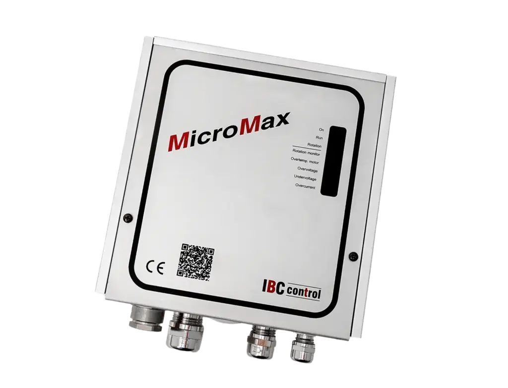
IBC MicroMax, MicroMax180, MicroMax370 and MicroMax750 units use a diagnostic LED system.
When a fault occurs:
- The green ON LED flashes
- One or more red LEDs indicate the fault type
- Alarms remain latched until manually reset
It is essential not to reset the unit immediately, always identify which LED is active before clearing the alarm.
Common LED indicators include:
- Rotation fault
- Motor temperature
- Overvoltage
- Undervoltage
- Overcurrent
Correct diagnosis begins with reading the LEDs accurately.
2. Troubleshooting Rotation Sensor Faults
A common issue during commissioning is a rotation sensor trip.
Possible Causes During Installation:
- Broken belt
- Belt slipping
- Stuck or seized heat recovery wheel
- Damaged motor or gearbox
Possible Causes During Operation:
- Magnetic sensor wired incorrectly
- Magnet facing the wrong direction
- Mechanical resistance in the rotor
How to Check the Magnetic Sensor
Measure voltage across terminals 9 and 10:
- Non-actuated sensor ≈ 10 VDC
- Actuated by magnet ≈ 2.7–3 VDC
Note from the IBC documentation: Older magnetic sensors (manufactured between 2006–2007) may lock at 2.7 V in extreme temperatures below -25°C. These should be replaced.
If readings are incorrect:
- Check polarity (white cable to terminal 9, brown to terminal 10)
- Inspect magnet alignment
- Replace faulty sensor
3. Motor Temperature & Thermal Contact Faults
If the motor temperature LED is triggered, the thermal contact in the motor has tripped.
Likely Causes:
- Rotor difficult to turn
- Gear jammed (no lubrication)
- Bearing failure
- Overloaded motor
The motor’s thermal contact resets automatically when temperature drops however, the alarm remains active until manually reset.
Diagnostic Procedure:
- Disconnect thermal contact wires (T-T).
- Bridge terminals T-T.
- Reset the control unit.
If alarm clears:
- Fault lies in motor or wiring.
If alarm remains:
- Control unit may be defective.
This structured testing avoids unnecessary component replacement.
4. Overvoltage & Undervoltage Alarms
Voltage disturbances are a frequent cause of nuisance trips.
Overvoltage Trip
If supply exceeds 276 V for 4–5 seconds, the unit trips.
Action:
- Measure incoming voltage.
- If supply is correct, control unit may be faulty.
Undervoltage Trip
If supply drops below 195 V for 4–5 seconds, the unit trips.
Action:
- Check mains stability.
- Inspect distribution board and incoming supply.
Both voltage conditions must be corrected before resetting.
5. Overcurrent & Short Circuit Diagnostics
Overcurrent protection differs by model:
- MicroMax → 1.2 A
- MicroMax180 → 2.4 A
- MicroMax370 → 4 A
- MicroMax750 → 7 A
The control unit limits current and trips after 4–5 seconds.
Common Causes:
- Jammed gear
- Heavy rotor load
- Bearing failure
- Motor winding fault
- Phase-to-phase short
- Phase-to-earth fault
Earth Fault Warning
If a phase-to-earth fault occurs:
- The unit trips immediately.
- Power must be switched off before reset.
To isolate the issue:
- Reset unit.
- Disconnect motor cables (U, V, W).
- Test control unit without motor.
If alarm disappears → motor fault.
If alarm persists → control unit fault.
6.
No LED Lit – Power Supply Checks
If no LEDs are illuminated:
- Measure voltage at terminals L and N (should be 230 V).
- Check internal fuse.
- If fuse intact and voltage correct → control unit likely defective.
Always verify power before deeper troubleshooting.
7. Wheel Rotating at 0% Signal
If the wheel rotates despite a 0% input signal:
Measure voltage across terminals 2–3:
- Should be below 0.07 V.
Possible causes:
- Residual voltage from control unit
- DIP switch misconfiguration
- Incorrect input signal scaling
IBC recommends checking High Speed and Low Speed DIP switches are set to OFF .
An input signal amplification card may be used if required.
8. Connecting & Troubleshooting VVX Motors
Correct wiring is critical.
Three-Phase Worm Gear Motors (90–750 W)
Designed for 3x230/400 V (Star/Delta).
Delivered from IBC wired in Delta (3x230 V).
All IBC control units supply 1x230 V single phase but internally generate 3x230 V.
Therefore: VVX motors controlled by MicroMax must remain wired for 3x230 V.
Smaller Geared Motors (25–60 W)
Designed only for 3x230 V.
Cannot be rewired for 3x400 V.
Single-Phase Worm Gear Motors
Used with MicroStart controllers.
Operate on 1x230 V.
Use start capacitor (located in motor or controller).
GEFEG Three-Phase Motors
Older IBC systems used GEFEG motors.
Replacement wiring must follow appropriate three-phase wiring method.
9. Measuring Motor Winding Resistance
Testing motor windings confirms internal integrity.
Procedure:
- Disconnect motor cables.
- Remove connection links in motor.
- Use Megger or universal tester.
- Measure resistance across phases U-V-W.
Resistance must be identical across all three phases.
If imbalance exists:
- Motor winding fault present.
- Replace motor.
This step avoids replacing control units unnecessarily.
10. When Should You Replace Components?
Replace magnetic sensors if:
- Locked at 2.7 V in cold conditions
- Incorrect voltage readings persist
Replace control unit if:
- Fault persists with motor disconnected
- Internal fuse intact but no operation
- Voltage input correct but no LED response
Replace motor if:
- Winding resistance imbalance
- Phase-to-earth short
- Bearing or gearbox failure confirmed
Conclusion: Structured Troubleshooting Saves Time & Cost
IBC MicroMax and VVX systems are robust, but faults must be approached methodically.
Correct troubleshooting involves:
- Reading LED indicators carefully
- Verifying supply voltage
- Testing thermal contacts
- Measuring motor resistance
- Isolating motor vs control unit faults
By following a structured approach, engineers can reduce downtime, prevent unnecessary replacements and restore heat recovery operation efficiently.
For IBC Control products visit our online store today:
https://www.i-acs.co.uk/store/ibc-controls.html